Introduction
A weir is one of the simplest hydraulic structures there is. It holds the water back on one side, and lets it pass over a fixed crest into the water below. From the bank, the result often looks trivial. The height difference may be less than a meter, the water below the structure looks smooth, and there is no obvious sign of danger. This is exactly why low-head weirs have a reputation among rescue services as drowning machines.
Two Kinds of Flow
The problem is created at the foot of the structure. On its way down, the water accelerates, so it arrives at the bottom fast and shallow, while the water it runs into, further along the same channel, is slow and deep. These two are not simply different in degree. They are physically distinct states of an open channel flow, and the danger comes from forcing one into the other over a very short distance.
The quantity that separates them is the Froude number. It compares the speed of the flow to the speed at which a wave can travel along the surface. In shallow water that wave speed depends only on the depth,
where g is the acceleration due to gravity and h is the water depth. The Froude number is the ratio of the flow velocity to this wave speed,
When the flow is slower than its own waves, the Froude number is below one and the flow is subcritical. A disturbance can still work its way upstream, and the flow is deep and unhurried. This is the ordinary state of a river. When the flow is faster than its waves, the Froude number is above one and the flow is supercritical. Nothing can travel upstream any more, and the water runs as a thin, fast sheet. The stream coming down a weir is supercritical. The slower, deeper water it runs into is not.
The Hydraulic Jump
The transition between the two is called a hydraulic jump. The water decelerates abruptly and becomes much thicker, and it does so violently, because most of the energy the flow gained on the way down is dissipated in the process. How thick it becomes is not a matter of chance. It follows from conservation of momentum, which fixes exactly one depth that a given supercritical stream can jump to, known as its conjugate depth. This conjugate depth is many times the thickness of the incoming sheet.
What happens next depends entirely on how deep the water below the weir actually is. If it happens to stand at the conjugate depth, the jump sits there as a visible breaking wave, and nobody would mistake it for calm water. If the water downstream is deeper than the conjugate depth, the jump has nowhere to stand. It is drowned. Instead of a wave on the surface, the fast stream dives underneath it and continues along the bed, while the water above is dragged back upstream towards the weir. This reversed surface current is the defining feature of the hydraulic roller. It is stable and self-sustaining, and it is quiet: the deeper the water downstream, the less the surface gives away about what is happening below it.
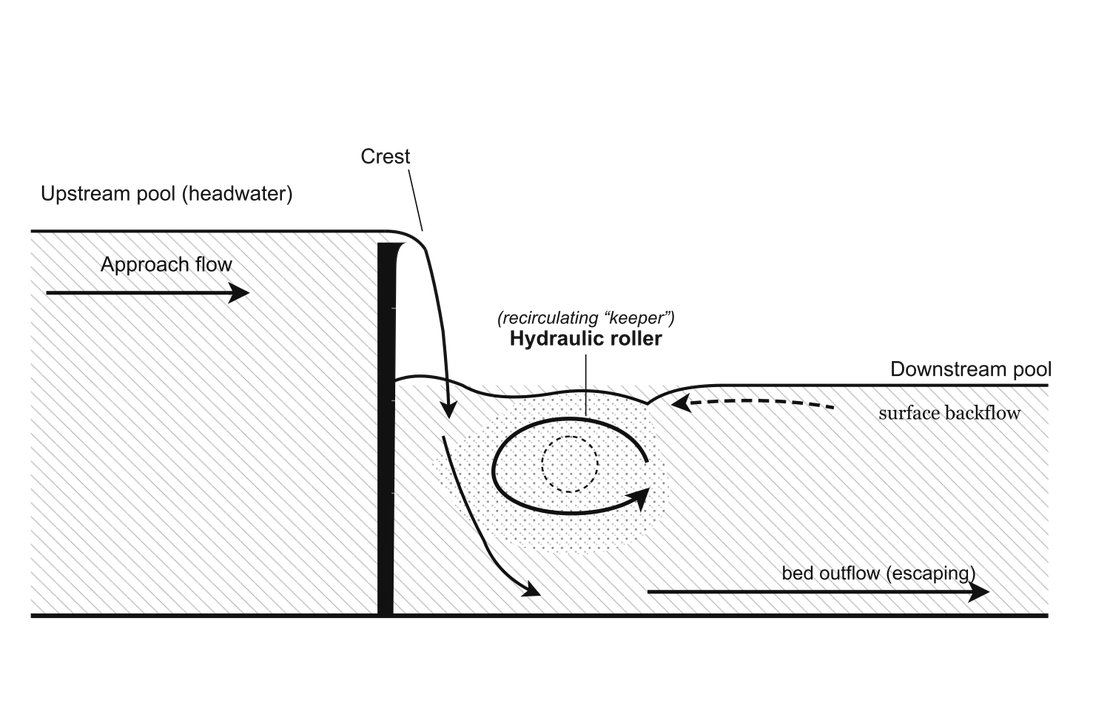
The schematic above shows the mechanism in a side view, with the flow running from left to right. The water passes the crest and plunges into the deeper, slower flow downstream. Near the bed it continues downstream and eventually leaves the zone. Near the surface it runs the other way, back towards the weir, and closes the circulation. Where the returning surface current meets the incoming stream is where floating objects are pulled under.
The drawing is generic and deliberately simplified. It shows a vertical face, but the mechanism does not depend on the water falling freely. What matters is only that the flow reaches the foot of the structure fast and shallow and has to give way to slow, deep water downstream. A sloping face, which is the geometry used in the simulation further below, produces the same roller. It can even produce a stronger one, because the water stays attached instead of breaking up in the air, so it loses less energy on the way down and arrives at the bottom with more momentum. It also entrains less air, which means less white water and a surface that gives away even less about what is happening underneath. The headwater pool on the right of the drawing is likewise only there to complete the picture. As the next section explains, the simulation does not model it at all.
Why the Roller Is a Trap
For anything floating, this is a trap. A swimmer, a kayak, or a piece of debris that enters the roller is carried back towards the weir by the surface current, pushed under by the incoming stream, transported downstream near the bed, and then lifted back to the surface at the downstream end of the cell, where the cycle starts again. The escape routes are limited and counterintuitive. Swimming towards the visibly calm water downstream means swimming directly against the returning surface current, and at the surface that return flow is the fastest current there is. The water inside the roller is also heavily aerated, so its effective density is reduced and buoyancy is far lower than in clear water, which makes staying at the surface harder than it would normally be. The only reliable escape is downwards and out along the bed, or sideways at the ends of the roller, and neither is intuitive to someone in distress.
What Makes It Hard to Predict
Whether a given weir forms a dangerous roller, how far downstream it extends, and how strong the return velocity becomes are all sensitive to the discharge, the geometry of the crest and the downstream face, and above all to how the tailwater depth compares to the conjugate depth. Small changes in downstream water level can move a structure from harmless to hazardous and back, which is why the same weir can be safe at one discharge and lethal at another. This sensitivity is what makes the case interesting for simulation: the relevant quantities are not the ones a simple weir formula provides, but the local velocity field, the extent of the circulation cell, and the trajectory of a floating body inside it.
Case Description
Setup
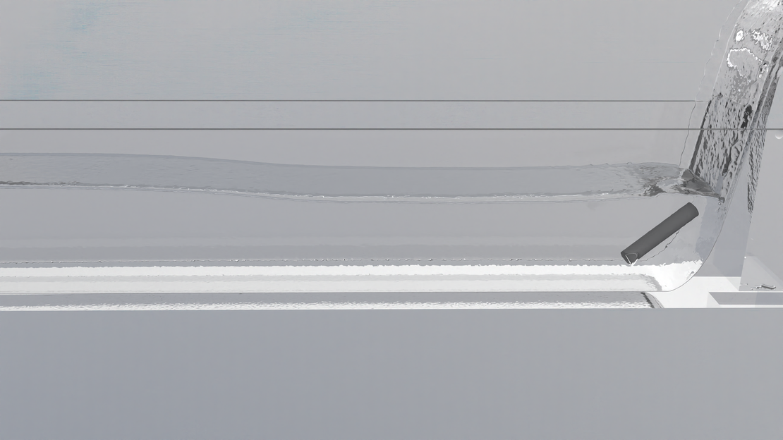
The simulation reproduces a laboratory-scale flume and models only the flow below the weir crest. The channel is 1 m long and 10 cm wide and starts pre-filled with water. A curved ramp 26 cm high stands at the upstream end, steep at the top and running out into the horizontal at its foot. Water enters through a rectangular inlet at the top of the ramp. A porous block spans the channel further downstream, and beyond it the channel ends in a free outlet.
| Parameter | Value |
|---|---|
| Channel, length × width | 1 m × 10 cm |
| Ramp height | 26 cm |
| Inlet, width × height | 9.3 cm × 3 cm |
| Inlet discharge | 35 l/min |
| Porous block, position | 0.7 m behind the ramp |
| Porous block, length × height | 5 cm × 14 cm |
| Darcy / Forchheimer / porosity | 5·10⁶ 1/m² / 1500 1/m / 0.4 |
| Fluid | water, 1000 kg/m³, 1 cSt |
| Particle radius | 0.75 mm |
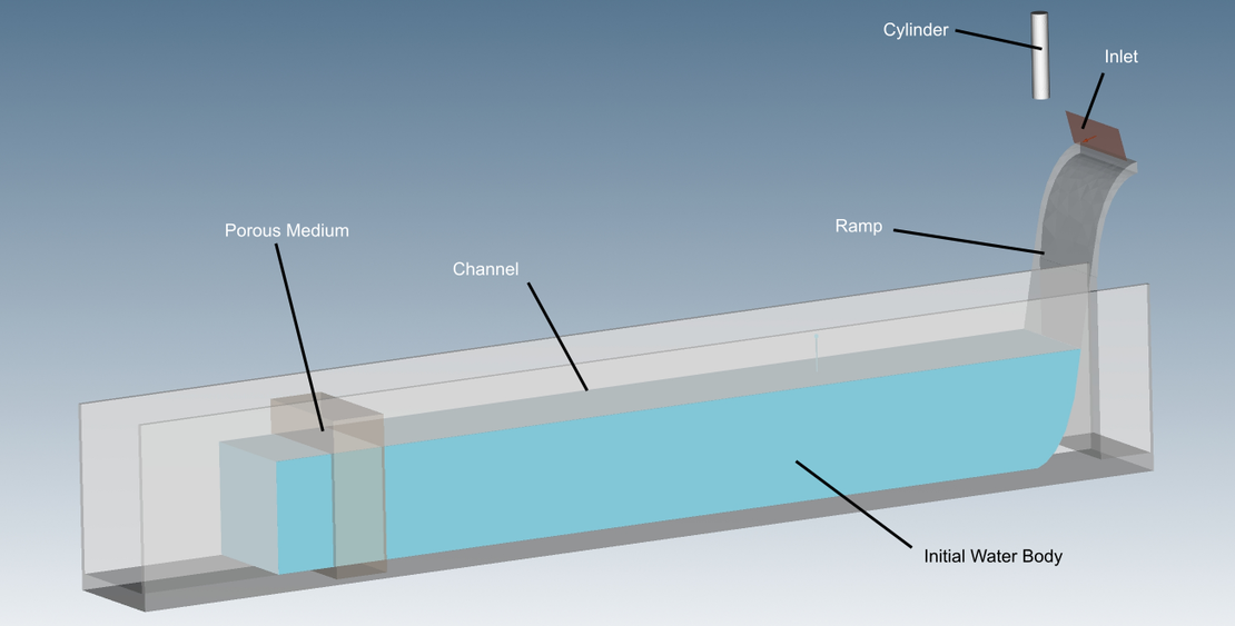
The run is transient and covers 40 s of physical time. A cylinder is released above the ramp after 15 s, once the flow has settled. It is 7.5 cm long, 1.5 cm in diameter, and has a density of 1100 kg/m³.
Modeling Choices
Three parts of the setup call for a justification: the missing headwater, the porous block, and the density of the cylinder.
The headwater is not modeled. What happens below a weir depends on how much water passes the crest and how fast, not on the reservoir that supplies it. A fixed inlet in place of the upstream pool spends the resolution on the flow of interest instead of on a large, near-stagnant volume.
The porous block sets the tailwater depth. A roller only forms if the water below the weir is deep enough to drown the hydraulic jump. In a short flume with a free outlet the water would run off and stay shallow, so a flow resistance is needed to hold the level up. The block stands in for whatever does this in reality, whether channel roughness, a downstream reach, or a second weir, and it sets the depth through a single physical parameter rather than an artificial boundary condition. Its Darcy-Forchheimer coefficients were tuned to give the required depth.
The cylinder is denser than water on purpose, for two separate reasons. The first is buoyancy. The water in a real roller is heavily aerated, so its effective density drops well below that of clear water, and a body that would float in clear water is pushed under. Raising the cylinder’s density reproduces this in a clear-water simulation, and does so conservatively: a body at 1000 kg/m³ in a mixture at 700 kg/m³ has a density ratio near 1.4, against 1.1 for the cylinder. The second reason is scale. At a diameter of 1.5 cm, surface tension and the contact angle are far stronger relative to the body than they would be for a full-scale log, and would hold a near-neutral cylinder at the surface. That is a model-scale artifact rather than a real effect, and a denser cylinder sits below it. Denser does not mean it sinks and leaves along the bed: the upward flow at the downstream end of the roller lifts it, the return current carries it back, and the incoming stream pushes it under again.
The Resulting Flow Regime
The water enters the domain slowly, at about 0.2 m/s, and gravity accelerates it down the ramp. Where it meets the surface it has reached roughly 1.9 m/s in a sheet about 3 mm thick, a Froude number near 10.
The ramp is 26 cm high, but the water downstream stands only 8 cm deep. The stream is accelerated by gravity over the upper 18 cm of the ramp, in contact with air, and enters the downstream water at the surface, 8 cm above the bed. From there it follows the submerged lower part of the ramp, which curves it from steep to horizontal. This is why the fast water ends up running along the bed instead of plunging into it, and why the roller can sit on top.
Such a stream would need a depth of about 4.8 cm to pass through a hydraulic jump into the downstream state. The sample line 25 cm behind the ramp shows a steady depth of 8.4 cm, about 1.75 times that value. The jump is therefore drowned. It cannot stand as a visible wave, and its energy feeds the roller instead.
Resolution
The particle radius of 0.75 mm places about two particles across the stream at its thinnest, where it enters the water, so the first instant of the impact is smeared. The stream thickens within a few centimeters, and the roller itself, more than 8 cm deep, spans over fifty particle diameters. The structure of interest is well resolved even where its inflow is not.
Limits of the Model
This is a single-phase simulation. The air is not modeled, so the heavy aeration of a real roller and the white water that comes with it are absent by construction, not merely mis-scaled. What the simulation reproduces correctly is the structure of the water flow, the position and extent of the roller and the reversed current. A separate and milder limitation is scale: at a water depth of a few centimeters, surface tension is disproportionately strong compared with a full-size weir. The case therefore demonstrates the mechanism rather than serving as a scale model in the sense of hydraulic similarity, and effects that depend on aeration, such as the reduced buoyancy inside a real roller, have to be accounted for separately, as they were in the choice of cylinder density.
Results
Reaching a Steady State
Before anything can be read out of the flow field, the simulation has to settle. The plot below compares the volume flow entering the domain through the inlet with the volume flow leaving it at the open end downstream of the porous block.
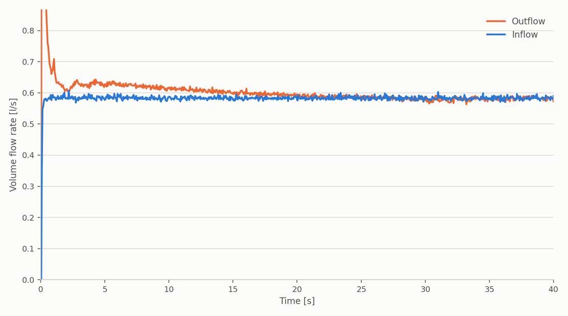
The inflow is a prescribed boundary condition and is therefore flat at close to 0.58 l/s, which is the 35 l/min the case is run at. The fine scatter on it is the particle discretization showing up in the flux through a fixed plane, not a fluctuating boundary condition. The outflow starts well above that value and decays towards it. The reason lies in the initial condition. The channel begins pre-filled, part of that initial water body sits downstream of the porous block where nothing holds it back, and the pool itself starts out higher than the level the block will eventually settle at. For the first seconds the channel is therefore releasing stored water on top of what it receives.
The gap between the two curves is exactly that release rate, and it closes after about twenty seconds. Two things follow from this. The first is that the channel has found its equilibrium: the pool has drained down to the depth at which the resistance of the porous block balances the incoming discharge, which is the 8.4 cm measured at the sample line. The second is a check on the simulation itself. The outflow converges on the prescribed inflow rather than on some value near it, which confirms that the free surface and the porous zone are not quietly gaining or losing water over a forty second run.
This is also why the cylinder is released at 15 seconds. By then the roller is fully developed and the remaining imbalance is down to a few percent, so what happens to the cylinder is a property of the established flow rather than of the startup.
The Roller
The image below shows pathlines through the developed flow, colored by velocity magnitude, with the ramp on the left.
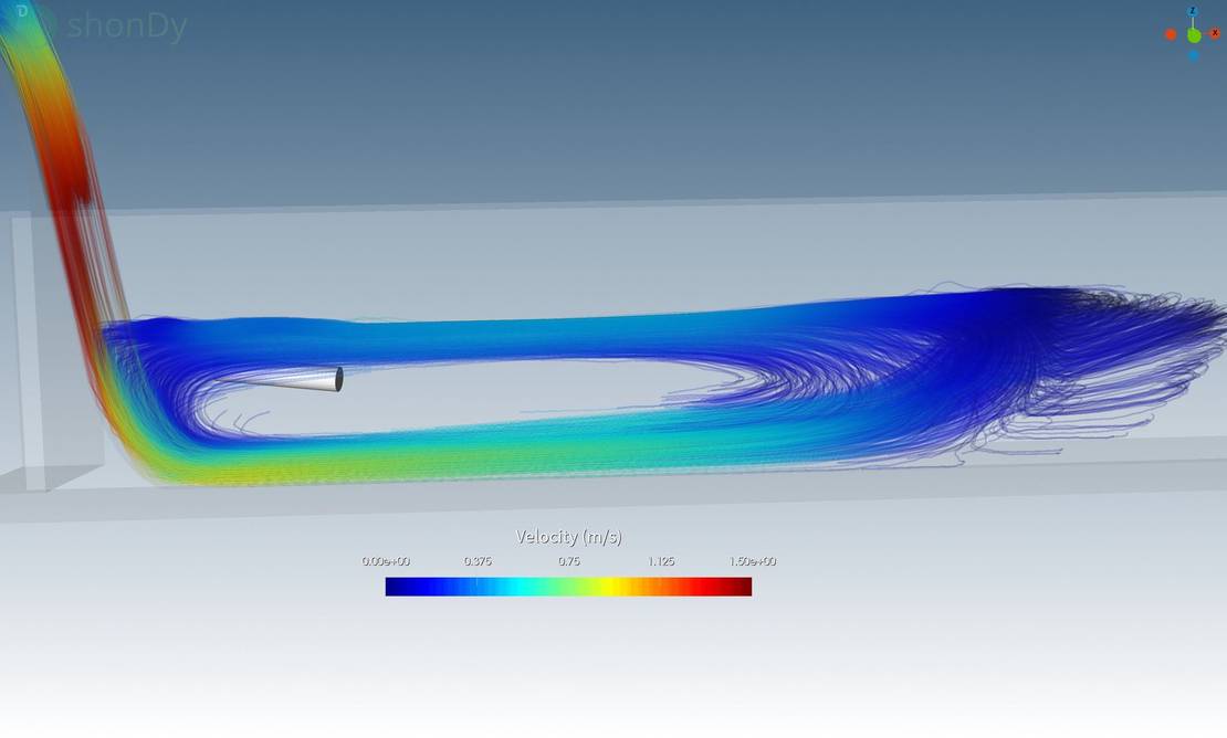
Everything the introduction describes is visible in a single picture. The stream comes down the ramp at the highest velocities anywhere in the domain, around 1.5 m/s and locally above it. That is somewhat below the 1.9 m/s that gravity alone would give over the 18 cm drop, the shortfall being friction along the ramp. At the foot it does not plunge into the bed. The curvature of the ramp turns it into the horizontal, and it continues downstream as a fast layer hugging the bed, still well above the velocity of the surrounding water.
Above that layer the picture reverses. The pathlines bend back towards the ramp and close into a large cell with a slow core in its middle and a return current along the surface. This is the hydraulic roller, and the cylinder sits inside it. Note how much slower the return current is than the stream that drives it. The energy that a free hydraulic jump would have dissipated in a visible breaking wave is instead spread over a long, slow, closed circulation, which is precisely why the surface above it gives so little away.
Further downstream the pathlines lose their order and the velocities drop towards zero as the flow reaches the porous block. The roller does not extend that far. It occupies the region immediately below the ramp and leaves a stretch of genuinely quiet water between itself and the end of the channel, which is the water that looks safe from the bank.
The Cylinder in the Roller
The video below runs from 10 to 40 seconds of simulated time and shows the cylinder entering the water at 15 seconds.
The cylinder is dropped at the ramp and is taken by the incoming stream and pushed under. From then on it follows the circulation rather than the mean flow: carried downstream near the bed, lifted at the far end of the cell, returned towards the ramp along the surface, and pushed under again. Over the remaining 25 seconds it does not leave the recirculation zone. In the same period, at 35 l/min through a channel holding about 8 liters, the entire body of water is exchanged roughly twice over. The cylinder sits in that water and makes no net progress at all.
The Mean Velocity Field
The pathlines and the video show the roller, but they do not measure it. To do that, the streamwise velocity was averaged over the interval from 20 to 40 seconds, well inside the quasi-steady window and long enough to cover several full turnovers of the flow. The figure below shows that mean field in the side view. Blue is flow heading downstream, orange is flow heading back towards the ramp, and the black line is the contour where the mean streamwise velocity is exactly zero.
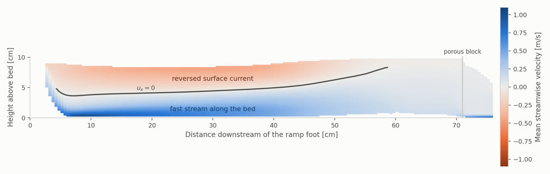
That zero line is the roller drawn as a measurement. Below it the flow runs downstream along the bed, fastest just behind the ramp, where the mean reaches about 1 m/s. Above it the flow runs the other way, back towards the ramp, and this is the reversed surface current. The two together close the recirculation cell. Reading along the surface, the return flow persists until roughly 69 cm behind the ramp, where the zero line finally climbs to the surface and the roller ends. In the rear third the fast stream lifts off the bed and rises towards the surface, which is why the strong colors near the bed fade out there.
The strength of the reversed surface current is what makes the roller dangerous. It peaks at about 0.44 m/s, directed upstream, back towards the ramp, and it runs right along the surface. This is the flow a floating body has to overcome to reach the calm water downstream, which is why an escape in that direction works against the strongest surface flow in the zone.
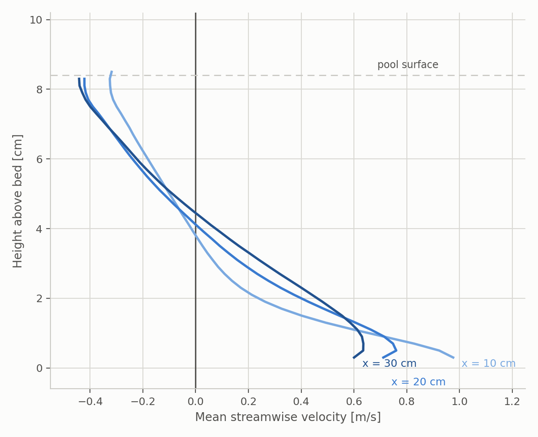
The depth profiles make the same structure quantitative at three stations behind the ramp. Each one crosses zero: positive near the bed, negative near the surface. The crossing sits a little below mid-depth and rises slightly with distance from the ramp, which is the zero line of the field seen edge on. The near-bed velocity weakens downstream, from about 0.9 m/s at 10 cm to 0.6 m/s at 30 cm, as the stream gives up its momentum to the surrounding water. The reversed flow at the surface, by contrast, stays close to its peak across all three stations, which is what makes it such a reliable trap over the whole length of the roller.
This is the field the cylinder was dropped into. Its path, described next, stays between 3 and 54 cm behind the ramp, entirely within the reversed-flow region mapped above.
What the Trajectory Shows
The center of mass of the cylinder can be tracked directly, which turns that observation into numbers. The figure below shows its path in the side view, colored by time.
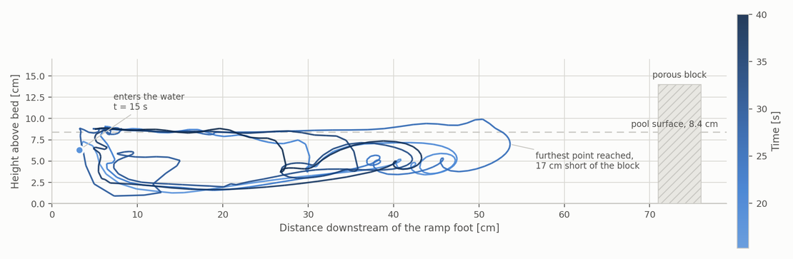
The path traces the roller itself. It reaches from about 3 cm behind the ramp foot to a furthest point of 54 cm, so the recirculation zone is roughly half a meter long, about six times the depth of the pool it sits in. In the vertical it covers almost everything available, from 9 mm above the bed to the free surface at 8.4 cm. The cylinder does not settle at one level and drift. It is cycled through the full depth of the zone again and again.
The color makes the second point. Light and dark loops lie on top of each other, which means the circulation is not decaying over the 25 seconds observed. The last circuit is comparable to the first.
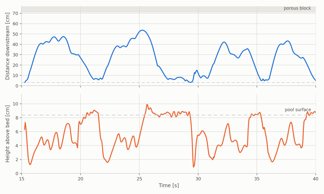
Plotted against time the motion is unmistakable. The cylinder completes four full circuits in 25 seconds, each taking between five and seven seconds. It travels downstream, turns, comes back to within a few centimeters of the ramp, and sets off again. The closest it ever gets to leaving is 54 cm, still 17 cm short of the porous block, and that excursion is followed by the sharpest return of the whole record.
The two numbers that matter are these. Along its path the cylinder covers 4.60 m. Its net displacement over the same 25 seconds is 1.8 cm. It travels the length of the channel more than four times over and ends up where it started.
That is the whole hazard in one measurement. The water is not holding on to the cylinder. It is passing through and leaving, and the cylinder is caught in a circulation whose only exit is along the bed, which is the one direction a person in the same situation would never choose.
One qualification. Across the channel the cylinder wanders irregularly over almost the full width, coming within a few millimeters of the side walls. That motion shows no correlation with the streamwise circulation, so the roller is not perfectly two-dimensional. The trapping mechanism is unaffected by it, but it is a reminder that the real structure is three-dimensional and that the side view above is a projection of it.
Summary
This case study simulated the flow downstream of a weir to show how the hydraulic roller forms and why it traps floating bodies. When fast, shallow flow meets slower, deeper water and the downstream level is above the conjugate depth, the hydraulic jump is drowned and turns into a closed recirculation cell with a reversed current at the surface. This roller is what gives low-head weirs their reputation as drowning machines, because the surface looks calm while the return flow at the surface carries anything floating back towards the weir.
The flow was modeled as a laboratory-scale flume with the particle-based solver shonDy. Only the region below the crest was simulated: a curved ramp with a fixed inlet replaced the headwater, and a porous block set the tailwater depth so that the jump would drown. The run was transient over 40 seconds, and after the flow had settled a slightly heavier-than-water cylinder was released at the ramp to act as a tracer for the trapping mechanism.
The results confirm the mechanism and put numbers on it. Inflow and outflow converge after about 20 seconds, which both establishes the quasi-steady state and verifies mass conservation over the run. The time-averaged velocity field resolves the roller directly: a fast stream along the bed, a reversed surface current peaking near 0.44 m/s, and a zero-velocity line that marks the boundary of the recirculation zone out to roughly 69 cm behind the ramp. The tracer never leaves this zone. Over 25 seconds it completes four circuits, covers 4.6 m along its path, and ends up 1.8 cm from where it started, while the surrounding water passes through the channel and out of the domain twice over.
Taken together, the simulation captures the free surface, the submerged hydraulic jump, the reversed surface current, and the motion of a floating body in a single transient run. This makes particle-based free-surface CFD a practical tool for assessing weir safety, where the quantities that decide whether a structure is hazardous, the local velocity field and the extent and strength of the roller, depend on discharge and tailwater depth in ways a simple weir formula cannot provide.