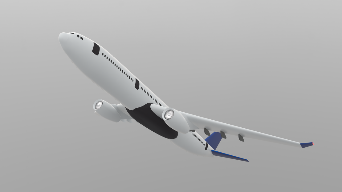
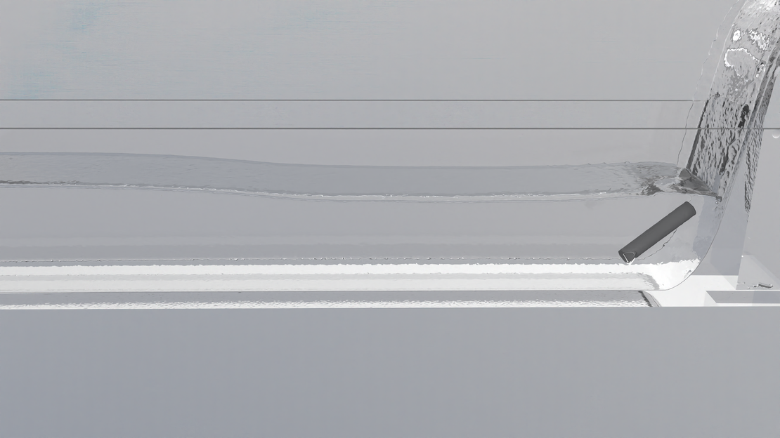
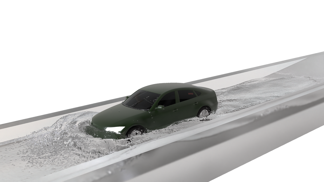
Amphibious water bombers such as the Canadair CL-415 refill their tanks without ever leaving flying speed. The aircraft touches down on a lake or river, skims across the surface “on the step” at 70 to 75 knots (~130 km/h), lowers two small scoop probes behind the hull step, and lets pure ram pressure do the rest: about 6,000 litres of water are forced up into the fuselage tanks in roughly 12 seconds over a run of some 400 metres. There are no pumps anywhere in this system. The dynamic pressure of the oncoming water alone lifts the entire payload into the aircraft.
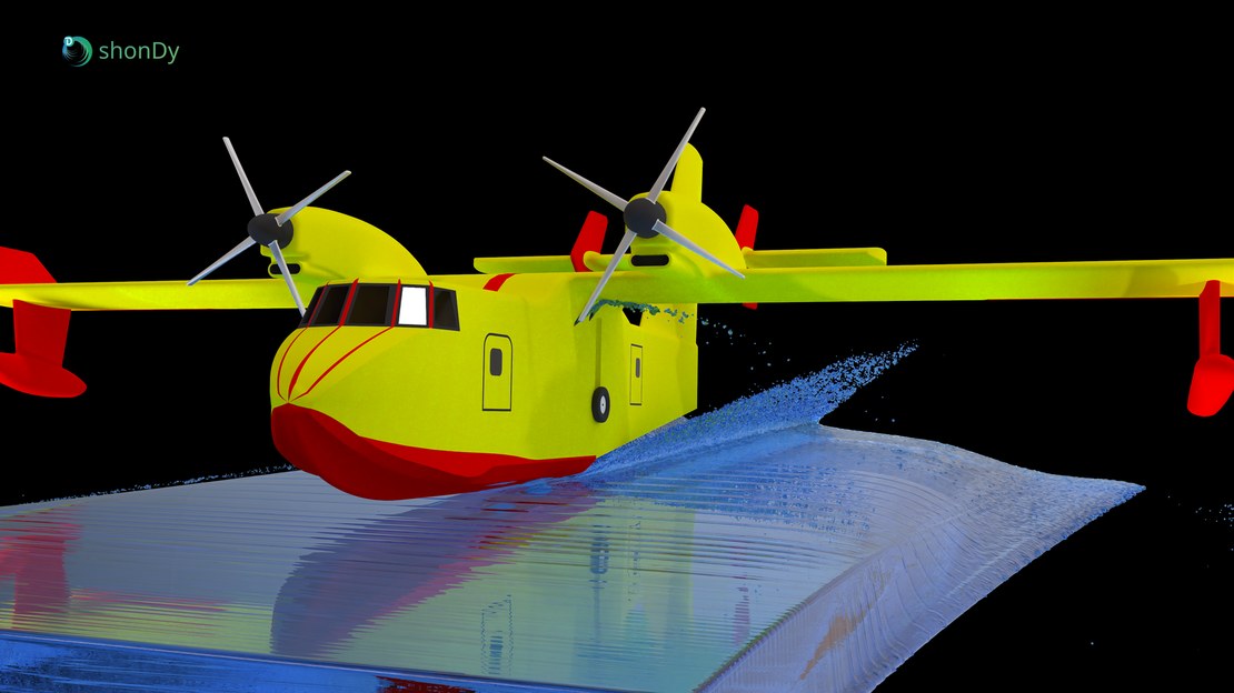
What makes this system remarkable is how small and how carefully shaped the intake is. Each probe presents an opening of little more than a hundred square centimetres to the water, no wider than a handspan, so that the aircraft at full power can just drag it through the water at minimum flying speed. The intake design works in two stages: a short 90° elbow redirects the water upward, and the water then leaves it as a free jet that rises inside a much larger receiver pipe for a substantial height before it first touches its wall. The probe exit reaches into the mouth of the receiver pipe but is separated from it by an annular gap, so probe and piping never touch and the drag of the internal plumbing cannot feed back onto the probe, which makes this design markedly more efficient than other scoops. The general idea of the probe system goes back to an early, expired patent from 1984.
A flow path like this is difficult to observe in reality: it is hidden inside the hull, submerged, and only active for a dozen seconds at 130 km/h. Simulation makes the entire chain visible in one continuous run: the flow at the probe mouth, the air space inside the elbow, the free jet transition into the riser, and the fill process inside the tank. This case study reproduces the complete scooping phase.
Case Description
Geometry
The simulation model uses a CL-415 airframe from a publicly available CAD model on GrabCAD. The complete internal water path was created specifically for this study and built into the CL-415 model. The outline and rough dimensions of the probe and receiver riser are inspired by the patent mentioned above (Hawkshaw / Field Aviation, 1984): the scoop probe with its semi-circular lower cross-section, the much larger receiver riser, and the annular gap between the probe exit and the surrounding riser mouth.
The tank proportions are plausible engineering estimates. From open literature it is known that the total tank volume is roughly 6,130 litres, divided into four separate tanks, with each of the two probes filling two of them, and that the four tanks can be emptied individually. Based on this, four simple tank geometries were designed, each holding a quarter of the total volume, connected only at the top so that they can still be emptied individually.
The ventilation and spill-over system was designed freely: images and videos of the scooping process show that displaced air, and once the tanks reach capacity the excess water, is released directly under the wing. The model follows this design choice in simplified form, with four pipes leading from the tanks to outlets just below the wing.
That said, the internals of the plane make no claim to represent the actual production aircraft; their purpose is to demonstrate the physics of the scooping process and shonDy’s capabilities in such an application scenario.
The geometry is shown in the images below:
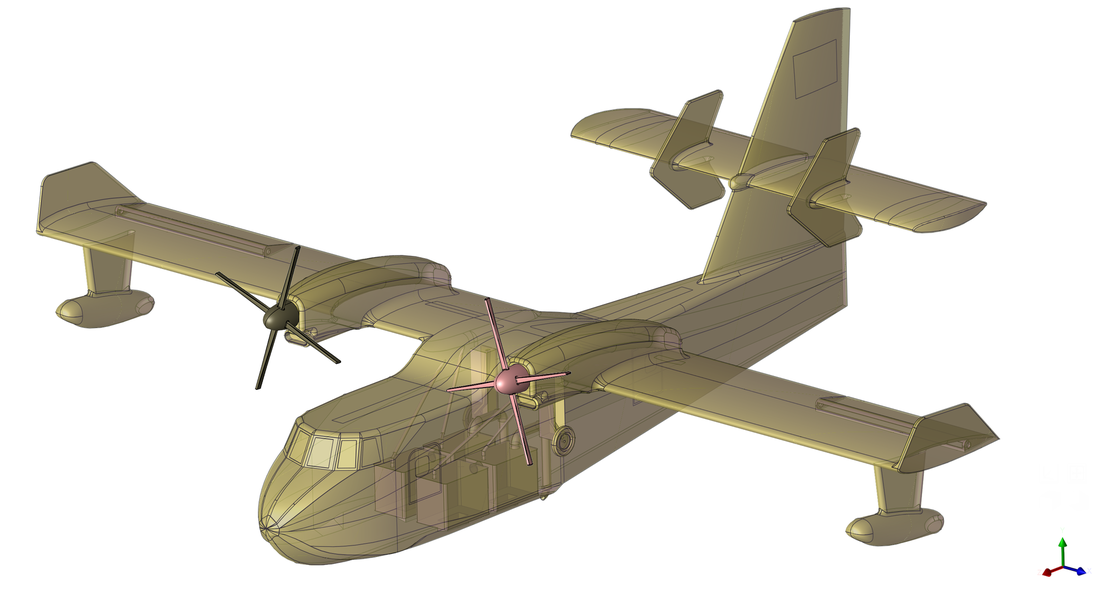
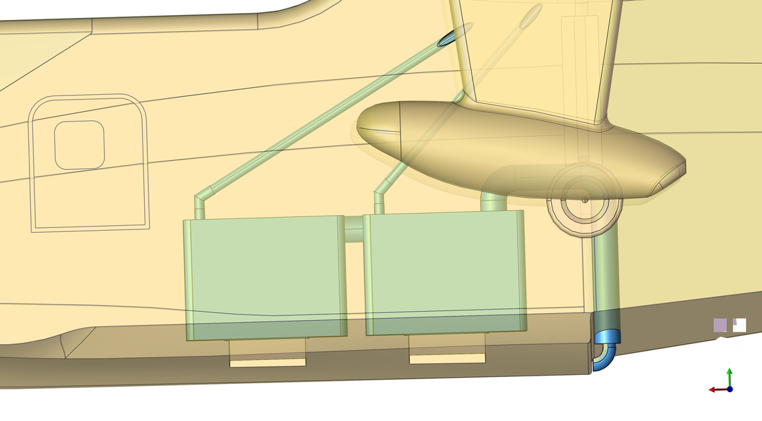
The airframe, including the internal piping and the tank walls, acts as a single rigid body in the simulation. The propellers rotate at a prescribed speed purely for visualization.
Simulation Setup: Moving Water, Stationary Aircraft
The basic idea of the setup is to keep the computational domain as small as possible. It mirrors a towing-tank experiment in reverse: instead of dragging the aircraft along a 400-metre scooping run, the aircraft stands still and the water moves. An inlet feeds water at a constant 130 km/h (36.1 m/s), the free surface develops naturally along the hull, and an outlet directly behind the aircraft removes the water from the domain again. For the fluid, the two situations are physically identical, but the stationary-aircraft formulation, with the airframe pitched 3° nose-up, the attitude of the real aircraft during the scooping run, shrinks the domain to little more than the dimensions of the aircraft itself, which cuts both computation time and memory.
For the first second of the run the probe openings are kept artificially closed, giving the water time to spread through the domain and the free surface time to develop along the hull. After one second the covers are removed instantly and the fill process starts. This has no counterpart in the real maneuver; it is purely a numerical measure to start the intake from a fully developed flow field rather than from the initial transient.
Two refinement regions halve the particle radius where the physics is decided: a first box encloses the probe and the flow beneath the hull step, a second one covers the intakes of the ventilation system. Everywhere else the coarser base resolution keeps the channel flow affordable. A sampling window across the left tank pair records the volume flow into the tanks and the accumulated water volume over time, providing the fill curve directly from the particle data.
| Parameter | Value |
|---|---|
| Fluid | Water |
| Fluid density | 998 kg/m³ |
| Kinematic viscosity | 1.0·10⁻⁶ m²/s |
| Surface tension | 0.07 N/m |
| Scooping speed | 130 km/h (36.1 m/s) |
| Pitch attitude | 3° nose-up |
| Base particle radius | 25 mm |
| Refined particle radius | 12.5 mm |
| Simulated time | 13 s |
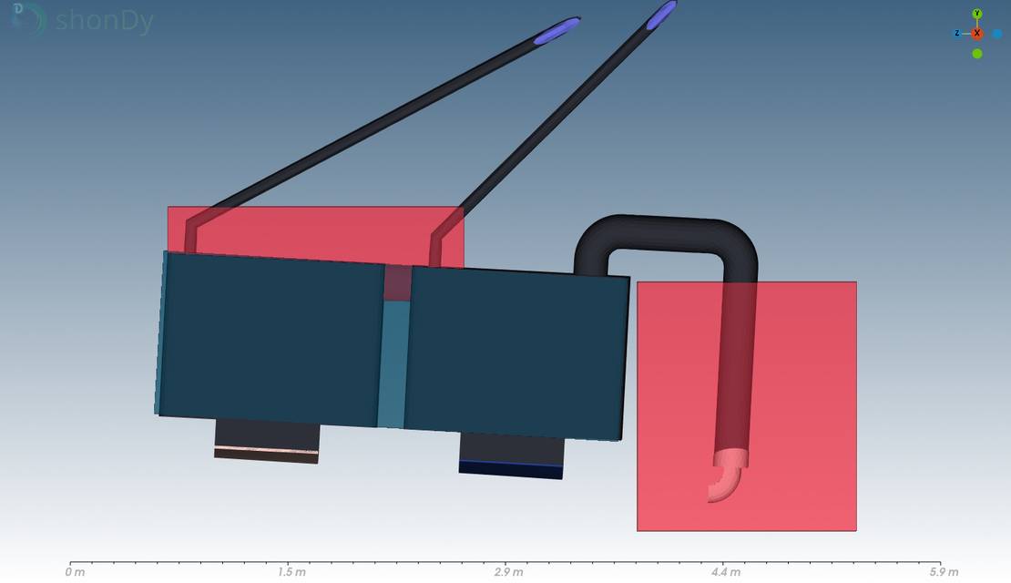
From the probe’s point of view, the run then unfolds in three stages, all captured in one continuous simulation:
- Intake: The water sheet coming off the step is redirected by the probe’s 90° elbow.
- Free jet: The water leaves the probe exit as an upward jet inside the receiver riser, whose cross-section of 410 cm² is roughly three times that of the probe. The probe exit sits inside the riser mouth, separated from it only by an annular gap, and the jet rises and expands freely before it first touches the riser wall, so no piping drag is transmitted back to the probe.
- Fill: Carried by its own momentum, the water rises through the riser, is turned by two bends, and drops into the tank cell from above.
Results
The Intake Chain at 130 km/h
The video follows the water through the complete intake chain:
- Hull flow: The oncoming water divides at the forebody, forms the characteristic spray pattern along the chines, and leaves the step as a coherent sheet directly in front of the probe mouth.
- Probe: The sheet is swallowed by the submerged elbow, which turns it upward through 90°.
- Free jet: Above the probe exit the jet rises freely inside the much larger receiver riser before it first touches its wall, without the probe ever touching the piping around it.
- Tank: The water rises through the riser, is turned by the bends, and plunges into the tank cells from above. The early fill is dominated by churning and splashing; as the level rises, the surface calms down until the first tank cell is nearly full. A strong jet then spills over from the first cell and fills the second one. Once both cells are full, the excess water escapes through the vent pipes under the wing.
Fill Rate and Intake Efficiency
The video below shows the complete fill process of the left tank pair:
The live diagram plots the accumulated water volume recorded by a sampling window around the two left tank cells. The fill starts at 1 s, when the probe covers open, and is complete roughly 10.5 seconds later. The sampled pair, about half the aircraft’s capacity, holds 3,200 litres; with both probes feeding their tank pairs in parallel, this corresponds to a complete load in the order of 10 seconds, right in the range of the roughly 12 seconds reported for the real CL-415.
On closer inspection the fill curve splits into two sections, separated at around 1,700 litres. Below this line the average fill rate is 323 L/s; above it, the rate drops to 295 L/s. The video shows the reason directly: at that point the first tank cell is full and the water has to spill over into the second cell. This transfer cannot quite keep up with the inflow, so water backs up into the riser and throttles the intake.
From the measured fill rate, the intake efficiency of the probe can be calculated: it describes how completely the probe uses its own opening. The reference value is the ideal flow rate, the volume that would pass through the probe opening per second if the opening were completely filled with undisturbed water arriving at the scooping speed:
Here is the frontal area of the probe opening (132.5 cm²), the cross-section it presents to the oncoming water, and is the speed of the aircraft relative to the water, i.e. the scooping speed of 130 km/h. The intake efficiency is the actually delivered flow, the measured fill rate , divided by this ideal value:
Averaged over the whole run the probe delivers about 310 L/s, an efficiency of 65%. Evaluated separately for the two sections of the fill curve, the efficiency is 67.5% while the first cell fills unhindered and 61.7% once the spill-over into the second cell throttles the flow.
These values sit at the lower end of the published range: the patent mentioned above claims up to 94% for its probe design, against 65 to 75% for conventional scoops, all measured against the same reference, the ideal flow rate. That the model stays below the patent value is plausible, for several reasons:
- Geometry and positioning: The probe geometry is only loosely based on the information in the patent, and its position on the hull was set by eye rather than optimized. In the end this is a case study built from publicly available information, not a reproduction of the production aircraft.
- Backflow into the riser: That water backs up into the riser once the first cell is full is clearly a flaw of the simplified tank design. This shows two things: the simulation delivers valuable insights and concrete starting points for optimization, and the geometry downstream of the probe is anything but trivial.
- Immersion depth and resolution: The efficiency reacts strongly to the immersion depth of the probe in the water sheet, which was set to a plausible estimate rather than tuned, and the finite particle resolution smooths the thin sheet feeding the probe. Since immersion depth is a free parameter of the setup, trimming it toward maximum efficiency is exactly the kind of study this model is built for.
Free Jet Behavior
One defining feature of this design is that probe and riser never touch. The probe exit reaches into the riser mouth, separated from the surrounding wall only by an annular gap, and the water crosses from one into the other as a free jet. To guarantee the free jet, the riser cross-section has to be significantly larger than that of the probe, and the first bend of the riser has to sit far enough downstream: in this case study the riser cross-section of 410 cm² is 3.1 times the probe exit area of 132.5 cm², and the straight riser section above the probe exit runs 135 cm up to the first bend, roughly ten equivalent probe diameters.
The close-up shows how the free jet behaves over the course of the run, and it passes through three distinct regimes:
- Free rise as designed: At the beginning of the run the jet rises through the entire riser without touching its wall; the first contact happens only in the bend. As described above, this regime lasts until the first tank cell is full.
- The riser floods from above: Once the first tank cell is full and water backs up into the riser, the same backflow that shows up as the break in the fill curve, the wall-contact point migrates steadily downward toward the probe exit.
- The gap as relief path: From about 11.5 s, when both tank cells are full, the water column reaches all the way down to the probe mouth and excess water starts to escape downward through the annular gap.
The last regime shows the second job of the gap. Its first job is drag decoupling: since probe and piping never touch, the flow losses of riser, bends, and tank can never load the probe through a rigid connection. Its second job appears when the system backs up: instead of a closed water column building up backpressure at the probe exit, the surplus simply leaves through the annular gap. With a cross-section of about 260 cm², roughly twice the probe exit area of 132.5 cm², the gap lets the excess water escape easily: the probe keeps scooping, and no stagnation point forms in front of it.
Summary
In this case study, the complete water-scooping run of an amphibious firefighting aircraft, loosely based on the CL-415, was simulated: from the free-surface flow along the planing hull, through the probe and its free jet, up to the filling of the internal tank, all in one continuous particle-based simulation.
The moving-water, stationary-aircraft formulation keeps the domain compact while reproducing the exact operating point of the maneuver: 130 km/h inflow and the 3° nose-up on-the-step attitude place the probe mouth into the water sheet leaving the hull step. Two refinement zones concentrate the resolution on the probe and the ventilation intakes, and a sampling window converts the particle data directly into the fill curve.
The numbers land where the real aircraft operates: the probe delivers an average of 310 L/s into its tank pair, an intake efficiency of about 65%, and fills the sampled 3,200 litres in about 10.5 seconds. Extrapolated to both probes, the complete load is on board in the order of 10 seconds, close to the roughly 12 seconds reported for the real CL-415. The close-up of the riser confirms the working principle of the patented design: as long as the tanks accept the flow, the jet rises freely for about ten probe diameters before its first wall contact, and once the tanks are full the annular gap takes over as a relief path, letting the excess water escape without loading the probe.
Case set-up
| Fluid | Water |
| Fluid density | 998 kg/m³ |
| Surface tension | 0.07 N/m |
| Scooping speed | 130 km/h (36.1 m/s) |
| Pitch attitude | 3° nose-up |
| Particle radius | 25 mm (refined to 12.5 mm) |
| Simulated time | 13 s |