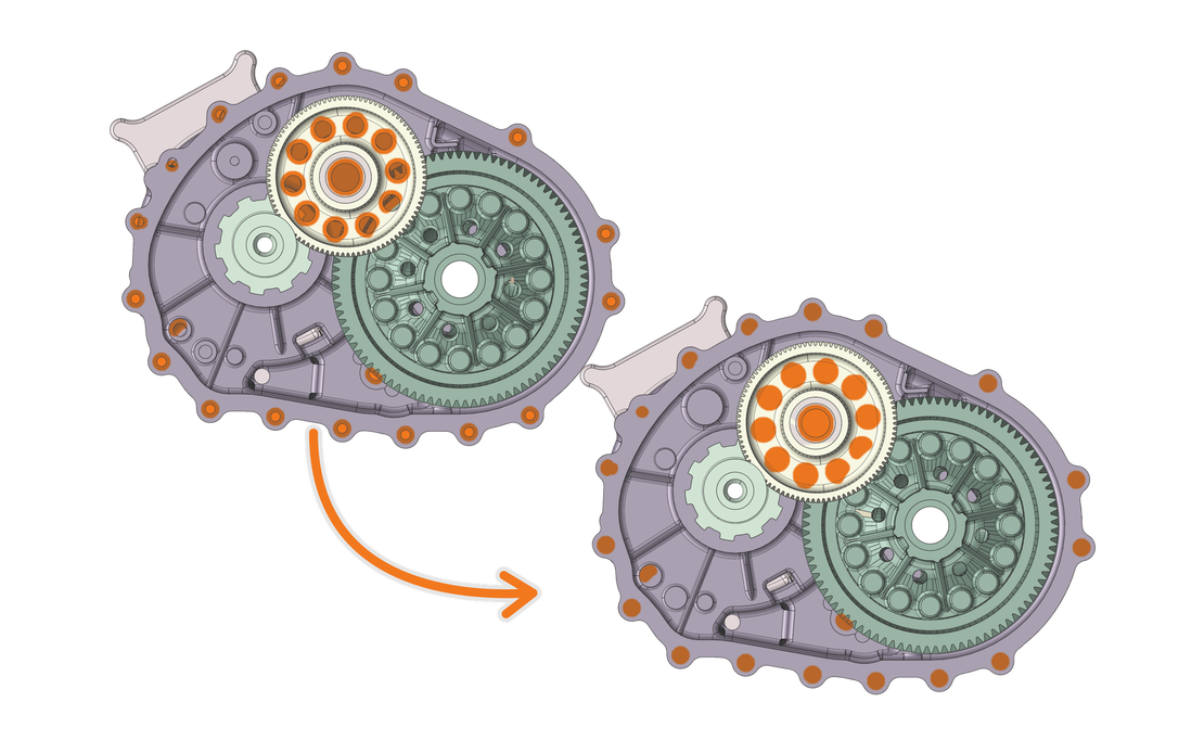
Geometry clean-up is usually treated as a chore that stands between the CAD export and the interesting part. It deserves a different reputation. Taking the time to prepare a geometry properly does two things for a simulation, and both of them happen before a single cell is meshed.
The first is that it forces the right questions early. What do I actually want to learn from this simulation? Which physics matter for that answer? Which geometric features influence those physics, and which ones are just there because the part has to be manufactured and bolted to something? Every feature you keep or remove is an answer to those questions, whether you asked them consciously or not.
The second follows from the first. Those answers decide whether the simulation becomes unnecessarily expensive. Every feature that stays in the geometry has to be meshed and then computed, in every iteration, for the entire duration of the project. A geometry that carries more detail than the question requires costs time twice: once in meshing, once in every run.
This is also where engineers grow. Asking these questions on every project is what turns an inexperienced engineer into an experienced one, faster, and into a better one. The comfortable alternative is to keep everything and let the mesher and the solver deal with it. More detail feels like more accuracy, but it is not: it does not automatically make the simulation better, it reliably makes it slower, and it shifts the problems downstream into post-processing, where the irrelevant detail now sits between you and the answer you wanted. The thinking itself cannot be delegated to software. What software can do is make it easy to act on: select the features that do not matter, remove them in one step, extract the domain the solver needs, and label the boundaries so the physics can be set up without guessing.
What follows is a practical walkthrough of the three steps that sit between a CAD export and a simulation-ready domain, whether that is a finite volume mesh of the fluid, a solid mesh for an FEM analysis, or a closed surface for a particle solver. Clean-up, as this article uses the term, means everything that happens to the geometry before the first element is generated: removing what does not belong, extracting what the solver needs, and labelling what the physics will attach to. One distinction is worth making up front. In a finite volume workflow, geometry preparation is non-negotiable: the volume mesh inherits every flaw in the surface, and this step decides whether there is a usable mesh at all. A particle-based solver is more forgiving, because it only needs a surface mesh of the solids, not a volume mesh of the fluid. That forgiveness tempts you to skip the thinking entirely. Resist the temptation. The questions above are worth asking either way, and simplifying where you can improves the quality of the simulation itself, not just the effort of setting it up.
The Problem With Raw CAD Exports
A CAD model is built to describe a manufactured part. A simulation is built to answer a question about physics. These are not the same objective, and a file that satisfies the first does not automatically satisfy the second.
Concretely, raw CAD exports carry two kinds of problems into the simulation. The first is detail that is essential for manufacturing and irrelevant for the physics: fastener holes, thread details, small fillets and chamfers, embossed text. The second is imperfection that the CAD environment tolerates but a simulation does not: gaps between surfaces where tolerances did not close cleanly, overlapping faces where two components were assembled without exact contact, duplicated or inverted surfaces. The first kind makes the simulation expensive. The second kind makes it fail: as a broken volume fill in a finite volume workflow, or, in a particle solver, as a gap in the wall through which the fluid quietly leaves the domain.
Step 1: Defeaturing and Repair
Defeaturing means removing geometric details that do not contribute meaningfully to the simulation result. Take a fastener hole on a casing wall. It has no influence on the flow physics, but the mesher still has to resolve its edges, build transition elements around it, and often refine the surrounding region to keep the element quality acceptable. One hole is noise. Dozens of holes and fillets on a typical industrial part add up to a measurable share of the mesh count and of the preparation time.
The rule of thumb: if a geometric feature is smaller than the resolution you intend to simulate at, it will either be resolved by a handful of badly shaped elements or force local refinement that multiplies your element count for no physical benefit. Neither outcome is free, and neither improves the result.
The harder part is knowing where to stop, because the answer depends on the physics. The practical question is always the same: at what length scale does a feature start to influence the result? For boundary layer flows, it depends on how the feature compares to the boundary layer thickness and the local velocity gradient. In internal flows through narrow passages, even small protrusions can redirect the flow. On the outer casing of a gearbox housing, where the simulation cares about bulk oil distribution, a row of mounting holes is irrelevant. The same logic runs in the opposite direction in a structural FEM analysis: a small fillet that is irrelevant for the flow may be exactly what controls the stress concentration, and removing it replaces a finite stress with a singular one at a sharp corner.
In practice, the call comes down to three questions:
- Remove a feature when it is smaller than your simulation resolution, sits outside the flow path, and carries no heat.
- Keep it when it meters a flow (orifices, oil bores), exchanges heat (fins, ribs), or forms a narrow passage the fluid actually has to pass through.
- When in doubt, ask what question the simulation is answering. The feature either contributes to that answer or it does not.
All of this addresses only the first problem class from the previous section, the detail that costs. The second class, the geometry that fails, is the job of surface repair: closing gaps between faces, removing duplicated surfaces, fixing inverted normals, and stitching the surface until it is watertight. The two operations are different in kind, but they belong to the same working session. A geometry that is clean but leaky is no more simulation-ready than one that is watertight but still carries every fastener hole.
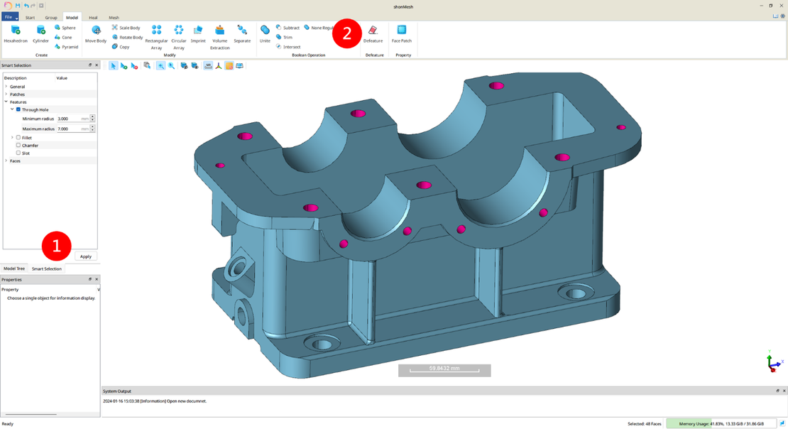
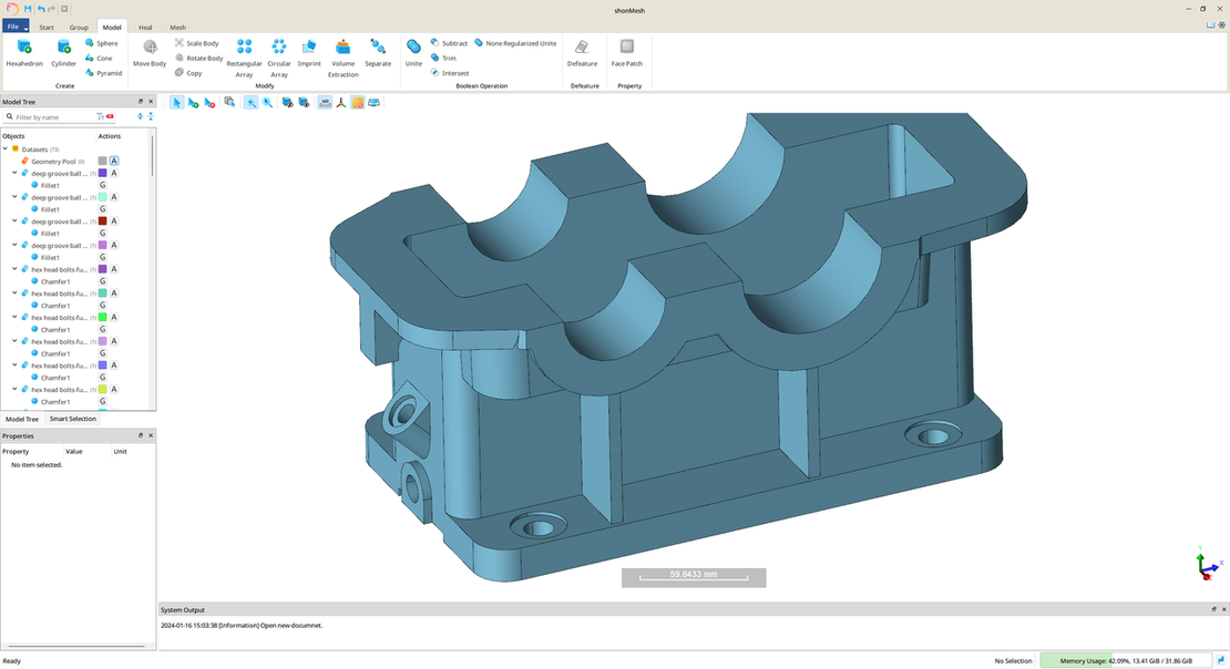
In shonMesh, the defeaturing workflow uses smart selection to identify features by attribute and removes them in batch. The result is a cleaned surface that retains the geometry relevant to the simulation and discards the rest. The defeaturing and grouping case study walks through this on an engine block geometry step by step.
Step 2: Volume Extraction
If you run a particle-based solver, this step does not necessarily apply: a particle simulation needs the solids themselves, not the fluid domain, though there are particle setups where an extracted volume is useful too, for example to fill an enclosed region with particles as the initial condition. The same is true for an FEM analysis: the solid itself is the domain, and no extraction is needed. In finite volume CFD, it is the other way around. The fluid domain is the essential part, and the fluid domain is what you mesh. The solid geometry is the boundary of that domain, not its content. The CAD file describes the solid; the simulation needs its inverse.
For simple external flow cases, this distinction is manageable. For internal flow problems like flow through a valve body, coolant through a heat exchanger, or a water jacket around a motor housing, the fluid domain is enclosed inside the solid geometry and has no direct representation in the CAD file. You need to extract it. And where fluid and solid are simulated together, as in conjugate heat transfer, you need both domains, cleanly separated and matching at their shared interface.
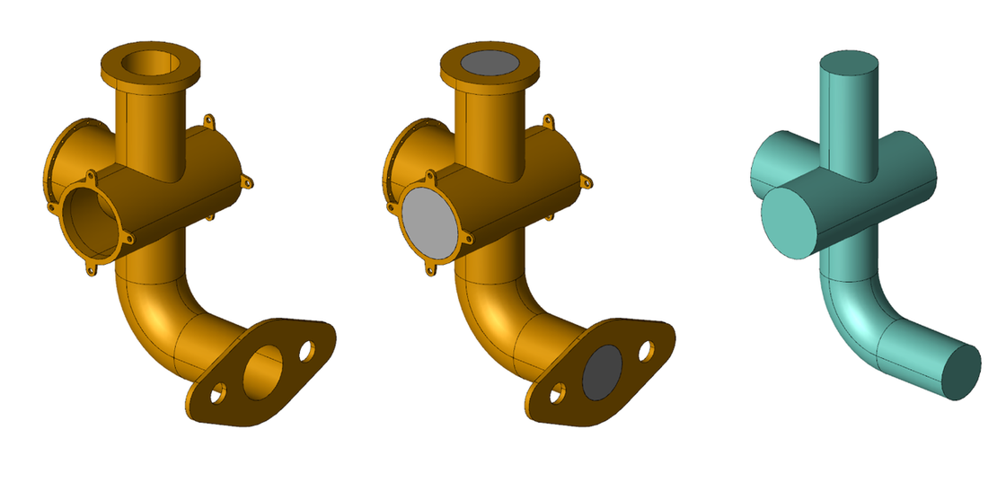
Volume extraction takes the closed solid geometry, identifies the enclosed space, and produces a fluid domain. In shonMesh, the volume extraction feature handles this in a single operation: the original geometry, the closed surfaces, and the extracted fluid volume are produced as a connected workflow output. The fluid domain can then be meshed directly without manual reconstruction of the interior surfaces. The volume extraction case study shows the operation on a pipe fitting.
Step 3: Boundary Grouping
The third step makes the last of the questions from the beginning concrete: which surface carries which physics? Before generating the mesh, surface patches on the geometry need to be grouped and labelled according to the boundary conditions they will carry in the solver. Inlets, outlets, walls, symmetry planes, rotating surfaces, and contact interfaces all require different treatment in the simulation, and that distinction needs to be encoded in the mesh before it leaves the meshing environment. This step, unlike volume extraction, applies to both solver families in full. In a particle-based lubrication case, the gear flanks are rotating walls, the oil injection nozzle is an inlet, and the housing is a static wall, and the solver can only tell them apart if the surface mesh says so.
The alternative, applying boundary conditions after meshing by selecting faces manually in the solver, is fragile. Face selections do not survive mesh refinement cleanly, are not reproducible across team members, and become unmanageable on geometries with many distinct boundary regions. Pre-assigning groups in the meshing tool means the labels are embedded in the mesh file and are automatically applied during import, regardless of mesh resolution or element type.
In shonMesh, boundary groups are set using the Face Patch function. Surfaces are selected, grouped, and named before mesh generation. The group labels carry through to the surface mesh and then to the volume mesh automatically, appearing as named boundary sets in the exported mesh file, ready to be mapped to boundary conditions in the solver without any post-processing.
The Payoff: Meshing Becomes the Easy Part
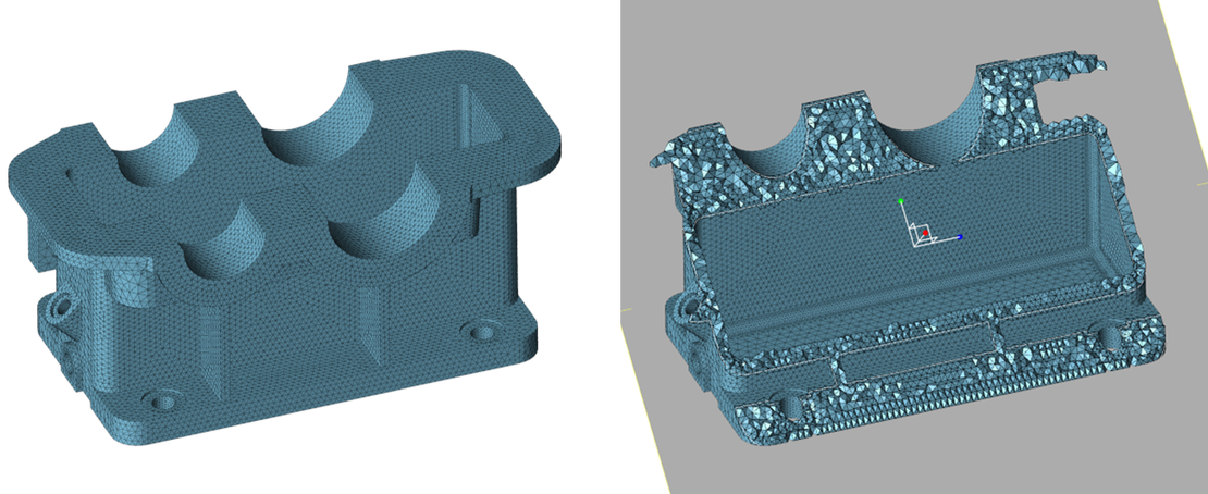
With the geometry defeatured and repaired, the fluid domain extracted, and the boundaries grouped, mesh generation stops being a troubleshooting exercise. In the case shown here, shonMesh builds a triangular surface mesh with global and local size controls, then a tetrahedral volume mesh of the solid on top of it, the mesh a thermal FEM analysis works on. A particle solver like shonDy needs no volume mesh at all: it works directly on the closed surface mesh. Whatever the target, on a prepared geometry this is the shortest part of the workflow. Not because the mesher works harder, but because there is nothing left for it to trip over.
Conclusion
Meshing literature tends to focus on element types, quality metrics, and refinement strategies, all of which matter, but none of which help if the geometry handed to the mesher is broken, over-detailed, or geometrically inverted relative to what the solver needs.
The three steps covered here, defeaturing with repair, volume extraction, and boundary grouping, are more than preprocessing. They are where you decide what the simulation is for, what it needs to resolve, and what it can safely ignore. Engineers who make those decisions deliberately get faster simulations and cleaner results, and they get better at making them every time they do. The tooling exists so that acting on the decisions takes minutes. The thinking is yours. The cases across the shonDynamics case study library follow exactly this sequence.
If you want to try this workflow on your own geometry, request a 3-week trial and an engineer will guide you through installation and your first case.