Splash lubrication in an EDU (Electric Drive Unit) is a harder problem than it looks. The oil has to reach the rotor bearings, coat the winding surfaces for heat dissipation, and supply transmission bearings across multiple shafts rotating at different speeds. The e-machine is fed actively, with oil supplied through the central rotor shaft and flung outward by centrifugal force, while the transmission bearings rely largely on passive splash from the sump. Either way, whether the oil reaches every surface that needs it depends on geometry, speed, and distribution patterns that are difficult to predict without resolving the flow in detail.
Intro
We ran the EDU as two coupled particle-based simulations: first the rotor shaft alone, to establish how oil splits across its internal channels, then the full machine, with the e-engine and transmission together, fed by those channel flows. (The published case study series splits this into three parts for readability.) The aim was to find out exactly what happens inside: what the rotor channels deliver, where winding coverage is highest and lowest, and which transmission bearings receive insufficient oil. This article is about what those simulations reveal, not about the method behind it. For why particle-based CFD suits splash lubrication and how it compares to mesh-based approaches, see our gearbox lubrication study and particle versus finite volume CFD.
What Makes an EDU Different
In a conventional gearbox, the lubrication objective is relatively focused: get oil to the bearings and gear contacts. The geometry is compact, the number of rotating components is limited, and the lubrication paths are well understood from decades of industrial experience.
An EDU combines an electric motor and a transmission in a single housing, so the lubrication system has to serve two fundamentally different functions at once. In the transmission, the lubricant reduces friction and wear at gear contacts and bearings. In the e-engine, its role is thermal: the oil has to coat the winding surfaces to carry heat away from a component that generates significant losses under load. These two requirements do not necessarily point toward the same oil distribution strategy.
The geometry is more demanding as well. Oil enters through the central rotor shaft, is flung radially outward through small internal channels, and from there must reach both the e-engine and transmission regions through a combination of direct spray, splash, and gravity-driven film flow, while multiple transmission shafts rotate at different speeds. That is exactly the kind of moving multibody, fragmenting free-surface problem particle-based CFD handles natively. What follows is what the simulation surfaced once we resolved it.
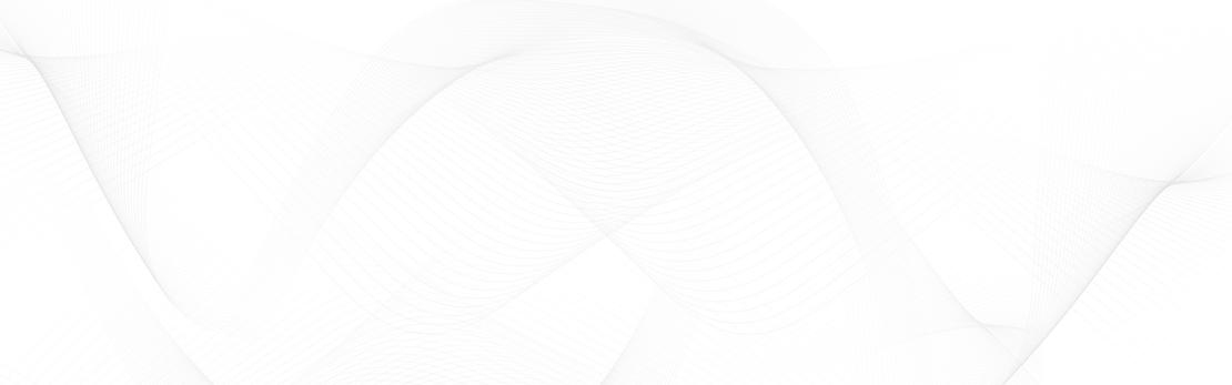
Rotor Channel Flow: The Boundary Condition Everything Depends On
Everything downstream depends on how the oil fed into the rotor shaft splits across the eight internal channels that carry it outward. Get that distribution wrong and the e-engine and transmission results rest on a flawed boundary condition, so the rotor is resolved first, on its own, and the channel flow rates it produces become the input to the full-machine simulation. Capturing those small channels accurately needs locally refined resolution; the full setup is detailed in Part I.
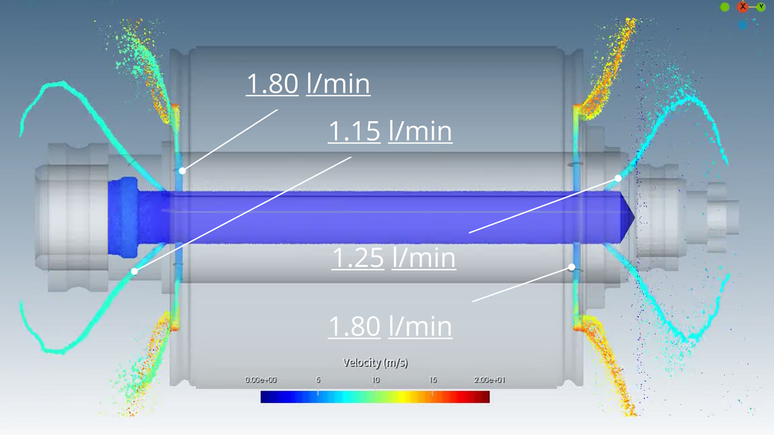
E-Engine: Winding Coverage Is the Thermal Story
With the rotor channel flows established, the second simulation covers the full machine, the e-engine and transmission together. Take the e-engine first. The question here is not just whether the bearings receive oil, but how evenly the winding surfaces are covered, because uneven coverage means uneven heat transfer, and a thermal model built on a single average heat transfer coefficient will miss the hotspots.
Both rotor bearings reach steady-state lubrication within the simulation window. The more revealing result is the winding coverage: it is highest at the winding ends, where the rotor flings oil directly onto the surface, and lowest in the central regions, which are shielded from direct spray by the geometry. That non-uniform pattern is a direct consequence of the spray geometry, and it is exactly the spatially resolved input a thermal model needs to assign realistic heat transfer coefficients across the winding rather than a single bulk value. We cover that handoff from oil distribution to component temperature in From Oil Distribution to Peak Temperature.
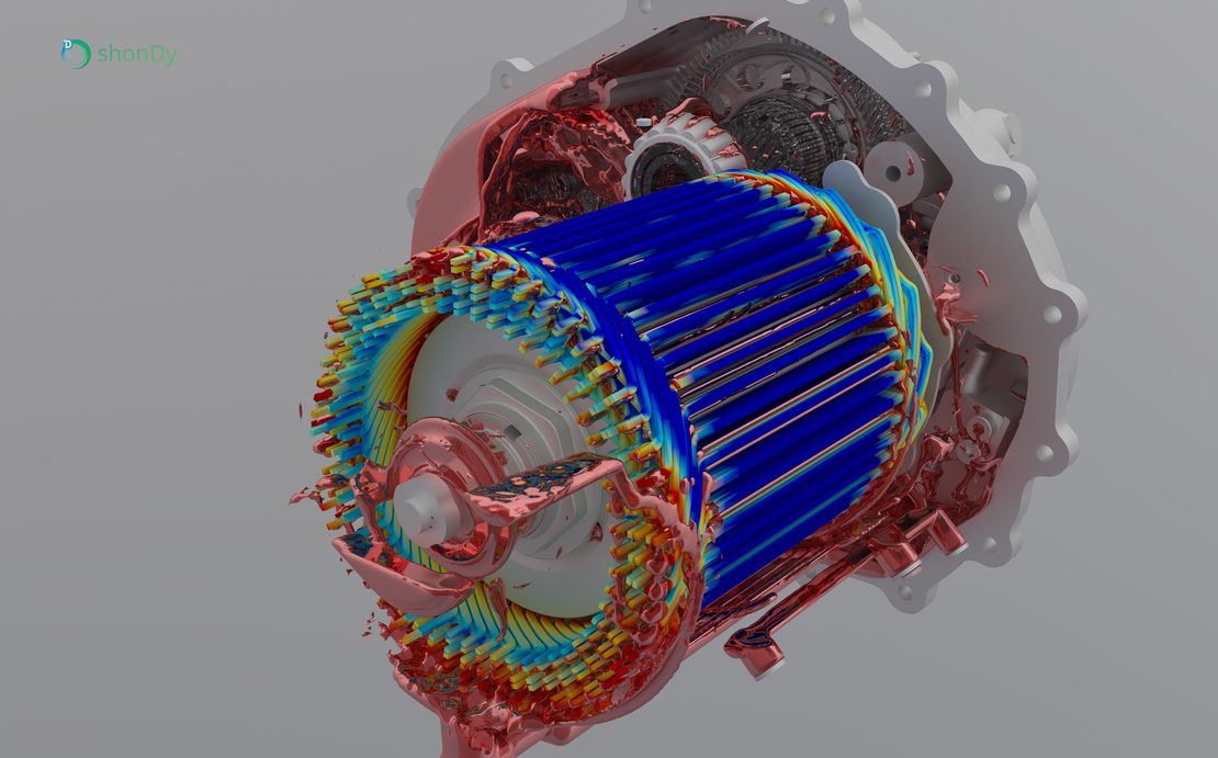
Transmission: Where Passive Splash Falls Short
Within that same second simulation, the transmission is where the most direct design finding emerges. Three shafts turn at very different speeds in a shared oil sump, fed only by passive splash.
Under passive splash the supply is markedly uneven. One bearing on the intermediate shaft receives no oil at all for the entire run, and a bearing on the input shaft stays well under-supplied, while the others reach a healthy steady state. These are not marginal differences, they are gaps the geometry creates, and the simulation surfaces them directly.
The output shaft shows the flip side, and the reason. It is the one shaft whose front bearing is better supplied than its rear, because a guide rail cast into the housing actively steers oil flung by the gear toward it. The lesson is transferable: where the geometry actively manages the oil path, the supply is reliable; where it leans on passive splash alone, it is not. The per-shaft bearing volumes are tabulated in Part III.
Putting EDU Design in Context
This two-part simulation shows what particle-based CFD offers beyond flow visualisation. The rotor channel flow rates feed the full-machine simulation. The winding coverage map feeds the thermal model. The transmission results point directly to where the geometry needs to be revisited.
Finding a completely dry bearing on the intermediate shaft is not the kind of result you get from a simplified analysis or an empirical estimate. Discovering it at the geometry stage costs nothing relative to discovering it after the drivetrain is assembled.
The full results, including flow rate diagrams, rendered bearing images, and winding coverage maps, are available in the EDU case study series:
- Part I: Simulating Lubricant Flow in the Rotor
- Part II: E-Engine, Winding Coverage and Bearing Supply
- Part III: Transmission, Bearing Lubrication Across Three Shafts
If you are designing an EDU or gearbox where passive splash lubrication is part of the strategy, request a trial of shonDy.